CMCRs 1 to 3 – Type 1
The first event that the BBC covered in colour was Trooping the Colour in 1967. The Type 1 CMCRs were fitted out in BBC premises and were equipped with four PC 60 cameras made by Philips and distributed in the UK by Peto Scott. The CMCRs followed the design of monochrome units with production and vision control across the width of the vehicle, allowing the only two colour monitors to be shared. Pye TVT supplied the sync pulse generator and sound mixer.
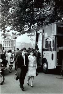
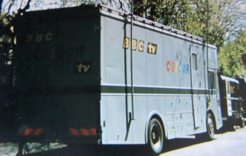
BBC Type 1 CMCR 1 at Trooping the Colour 1967
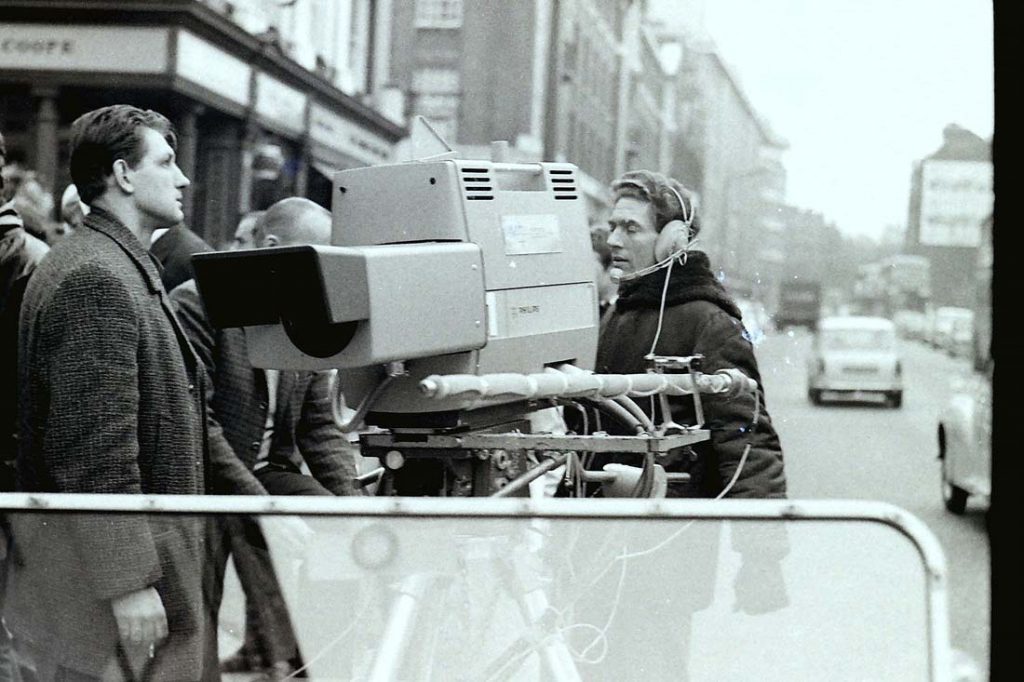
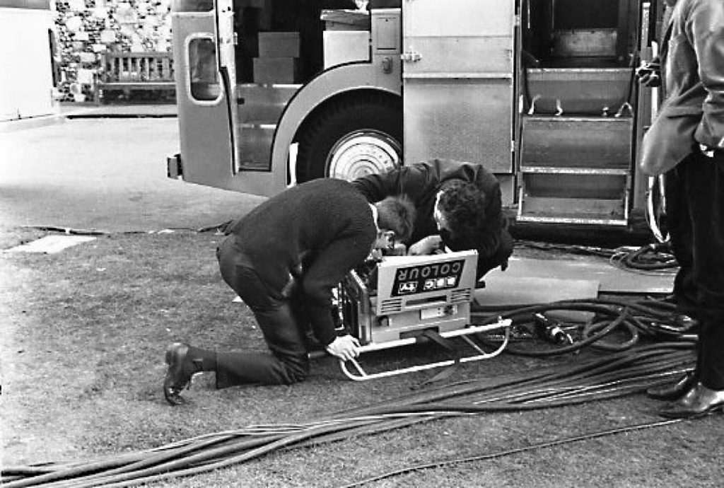
A Philips PC60 Camera with its two camera cables
CMCR 1 – photo: Andrew Brown
CMCR 1 – photo: Andrew Brown

LO1 Type-1 CMCR1 (left) with MCR19 at Trooping the Colour 1967
Notes on a visit to an O.B. at Canterbury Cathedral
by Geoff Dawe 13/6/68
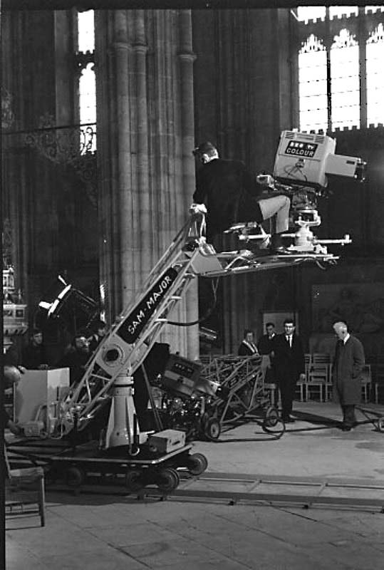
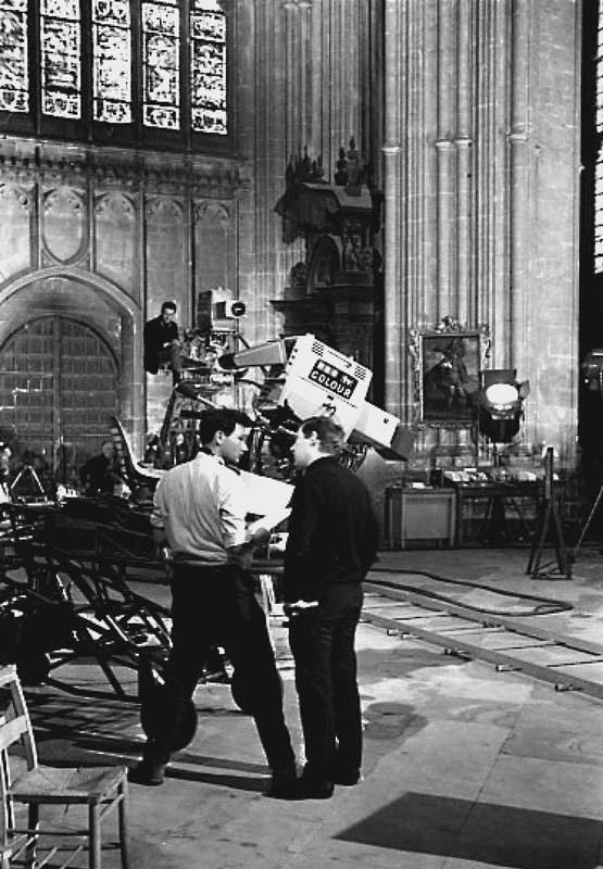
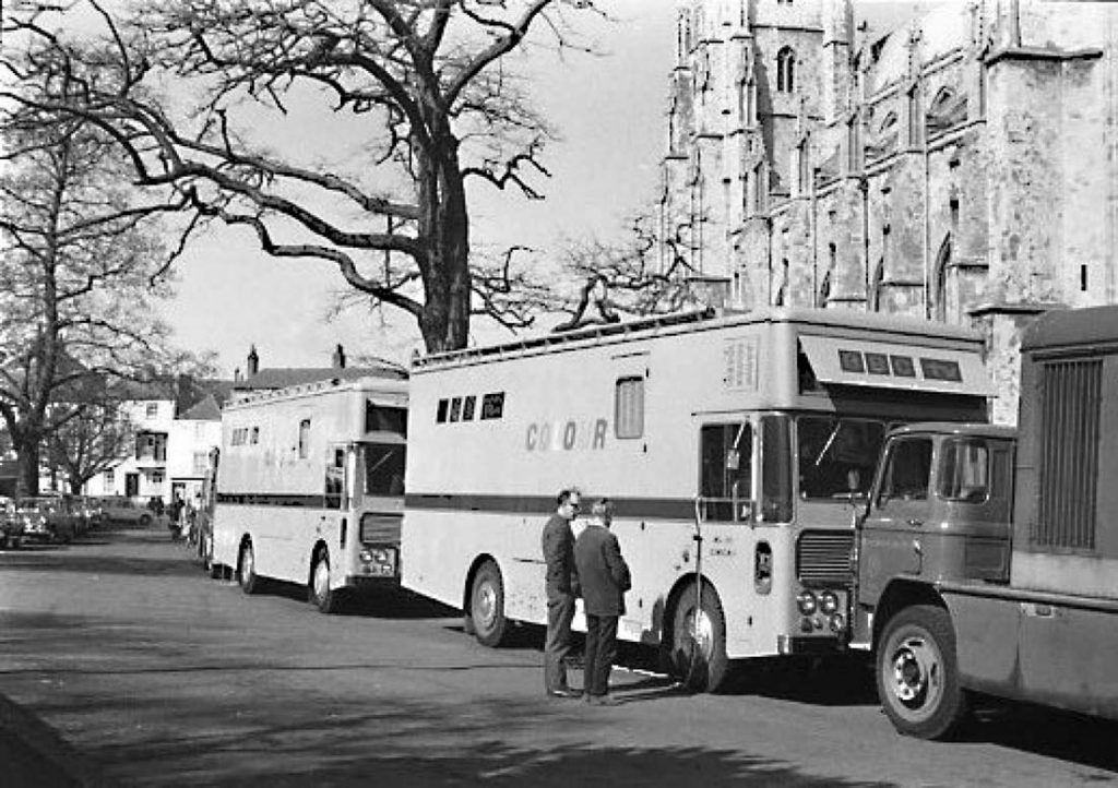
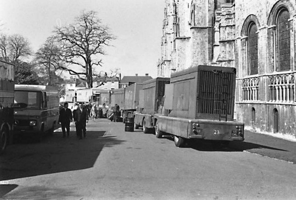
I visited Canterbury on 26th March 1968 during the recording of “Dream of Gerontius” by CMCRs 1 and 3 for broadcast on Easter Day. The technical vehicles were parked in the Cathedral Close and comprised CMCR1, CMCR3, the mobile sound control room, a mobile VTR, a GPO vehicle and five 100 KVA diesel generators for the lighting. The latter were supplied by Mole Richardson Ltd.
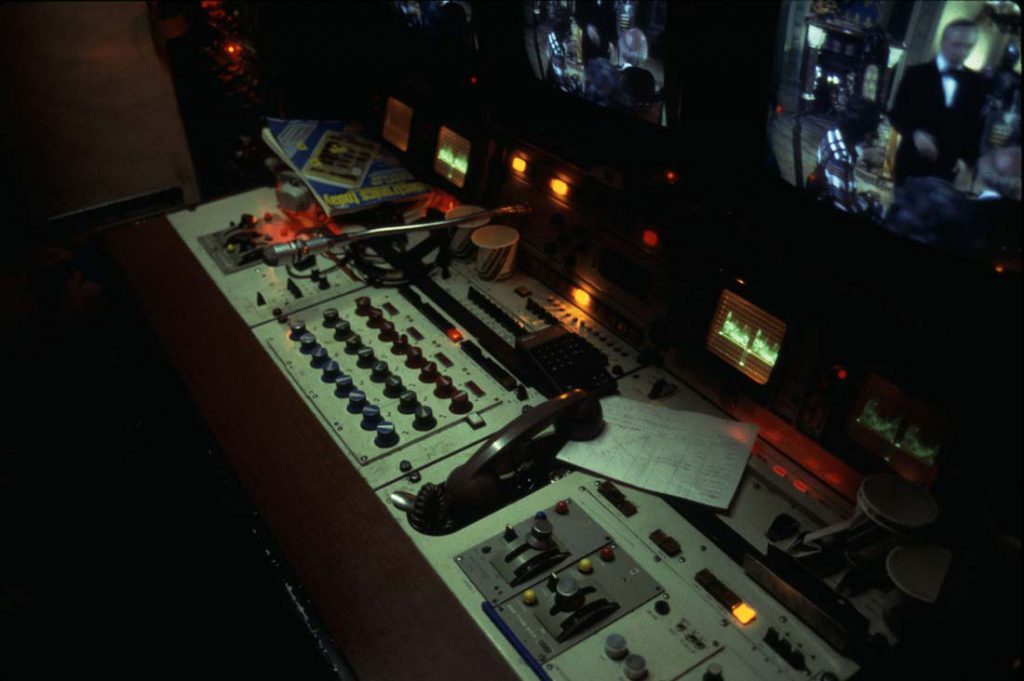
1. Vision System
CMCR 1 was the master MCR and vision mixing was carried out in this vehicle. The vision sources used were CMCR l’s own cameras (as cameras 1 to 4) and two cameras from CMCR 3 (cameras 5 and 6). The outputs of the two CMCR 3 cameras were fed coded to CMCR 1 via the normal external input arrangements on CMCR 1. In order to achieve correct timing for all sources, the drive unit and S.P.G. on CMCR 3 were used to originate pulses for both CMCRs. Both pulses and coded outputs from the cameras on CMCR 3 were thus delayed by the same amount when arriving at CMCR 1. Since this method of timing is not accurate enough to cope with subcarrier phase, a manual subcarrier phase shifter was used in CMCR 1 to phase shift the incoming subcarrier from CMCR 3 such that cameras 5 and 6 were in phase with cameras 1 to 4 at CMCR l’s mixer.
The coded feeds from CMCR 3 to CMCR 1 were not equalised and this resulted in a slight desaturation of these two channels. It may well be necessary to use equalisation on short runs between vehicles such as this. The new small size fixed equalisers being developed by Designs Department may well assist in this if a standard length cable harness can be used.
A third camera in CMCR 3 was used as a vision cue to the organist (who was in another church in Canterbury) to see the conductor in the Cathedral. This function was entirely closed circuit and the camera was simply locked in position looking at the conductor.
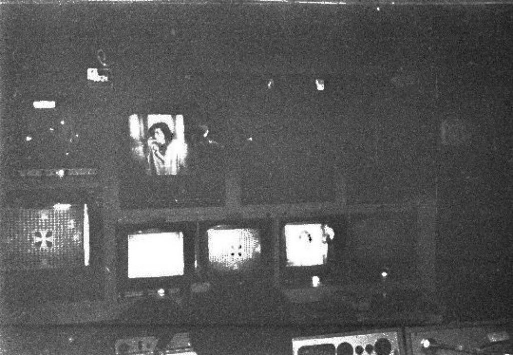
In CMCR 1 a third colour monitor was installed in place of the19” monochrome compatibility monitor to ease the monitoring of the 6 cameras. It was made switchable by the E.M.
2. Sound
The mobile sound control vehicle was used for sound mixing purposes and the sound desks in CMCRs 1 and 3 were not used. Since the producer was in CMCR 1, talkback and communication facilities on this CMCR were used to the full.
In addition to the vision cue feed to the organist mentioned above, there was of course a reverse sound feed.
3. General
The programme contained many shots of the architecture and windows of the cathedral and at least one camera was mounted on an up-pan wedge to facilitate shots of the vaulted roof. In addition to the more conventional shots of choir, orchestra, soloists and the building, the producer used several Strand Electric optical effects generators in order to produce blurred colour patterns which he superimposed on his other shots. This was done by the simple expedient of projecting the moving coloured patterns on white screens and using two cameras to look at the screens.
The cameras were scattered throughout the building and were mostly mounted on tripods. Two cameras in the nave, however, were mounted on dollies, one of which was a (hired) crane type dolly running on rails.
The large amount of lighting equipment was controlled by the use of simple dimmer trucks in the cathedral and would have much benefited from the use of remote controlled dimming equipment. In order to obtain better control of the light conditions many of the nave windows had been covered with black p.v.c. to prevent sunlight from reaching the performers.
On the day of my visit camera rehearsals only were taking place and thus I was not able to see any of the programme recorded. It was nevertheless most instructive to see the whole system working.
Notes on a visit to the Eurovision Song Contest at the Albert Hall
Following my visit to Canterbury I also paid two visits to the installation for the Eurovision Song Contest at the Albert Hall. In many ways this was similar to the Canterbury OB in that once again two CMCRs were used. As before the slave CMCR supplied the pulses and all cameras were directly available on the master CMCR mixer. All eight cameras were used on this occasion although one of these was a working spare. Once again the mobile sound control room was used, but on this occasion the sound installation was complicated by the need for Eurovision commentaries in many languages. The Eurovision equipment was housed in one of the bars of the Albert Hall, and I did not have time to see it.
The vision system was complicated by two factors which did not arise at Canterbury. The first was the need for a fully synchronous feed of telecine in the programme, and the second was the use of the slave MCR mixer as a reserve.
1. Natlock
In the absence of coders and decoders for the full colour natlock system, a hybrid system was employed. One of the 625 pulse chains at Television Centre was locked to the CMCRs in the normal monochrome natlock fashion, Le. a GE1/523 sync. comparator was used at the CMCRs to send an audio signal to the Television Centre where a UN17/508 audio decoder unit and a UN17/509 oscillator corrector operated on the GE1/520 waveform generator drive unit. Subcarrier phasing was then achieved in a “genlock” manner. The subcarrier from the incoming telecine signal was compared with local subcarrier by an EP5L/505 and the error signal was used to phase shift local subcarrier passing through an EP1L/509 digital phase shifter. To take account of local line lengths within the CMCR a variable lumped delay line was placed in front of the feed of syncs. to the GE1/523 and a manual subcarrier phase shifter was placed in the feed of subcarrier to the EP5L/505. When the installation of natlock is complete within the CMCRs it will be possible to cut lead lengths and insert fixed delays to make the timing correct.
2. Reserve Mixer
All sources were timed and phased to be synchronous at CMCR l’s mixer and it was therefore impossible to time and phase the same sources at CMCR 3’s mixer without the use of many delay lines. It was decided therefore to make the CMCR 1 cameras (Cams. 1-4) appear nonsync at CMCR 3’s mixer and CMCR 3’s cameras (Cams. 5-8) appeared in the first four positions on ‘synchronous only’ channels on CMCR 3’s mixer. In the event of a breakdown, the producer would thus have had to use a mixer on which the positions of the cameras had been reversed.
As at Canterbury, a third colour monitor was used in CMCR 1.
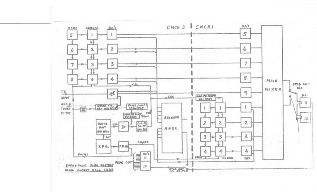
A block diagram of the installation at the Albert Hall is attached, showing the manner of linking the two CMCRs and the method of feeding pictures to line and to many local destinations. It was noted that all the available lines to the vision termination panel on CMCR 3 were used and many lines were not used for their designated purpose. Some comment was made on this fact by Tel. O. B. staff, but I feel that more logical use could have been made of the existing lines if the whole system had been planned beforehand. It is worth noting however, that the total number of lines is only marginally sufficient.
Photos and Diagram – Geoff Dawe

Type 2
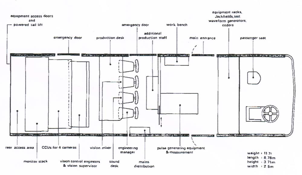
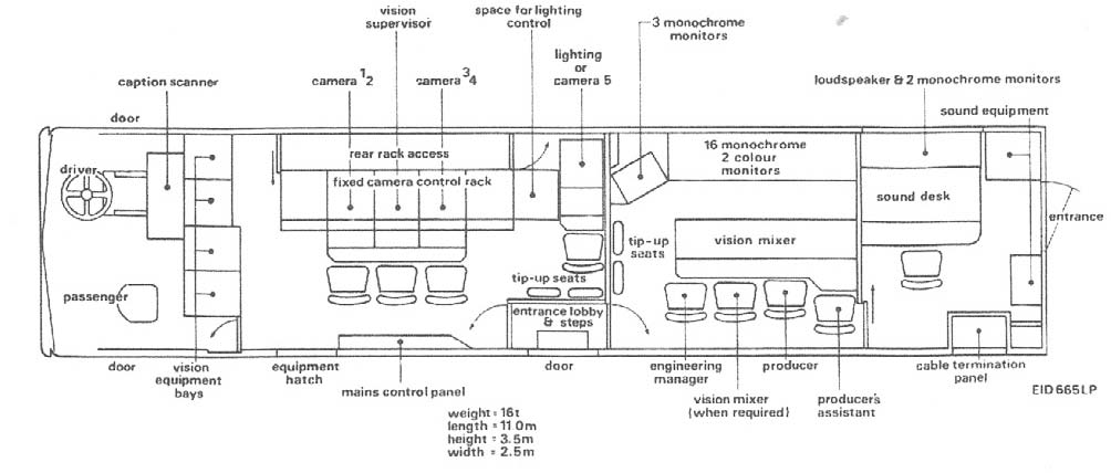
The BBC contracted PYE TVT to construct these nine units. They were designed to control up to six cameras and had a 23 channel Pye sound mixer. The coachwork was done by Bonallack’s. The majority of the control rooms were supplied with EMI 2001 cameras but three were equipped with Pye PC 80s (Philips LDK3s). The standard complement was four cameras but the units could accommodate up to six.
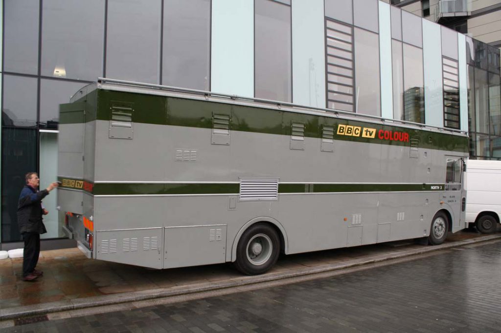
BBC Type 2 CMCR 9 / North3, Restored by Steve Harris with Jerry Clegg at the rear door. photo Louis Barfe (2012)
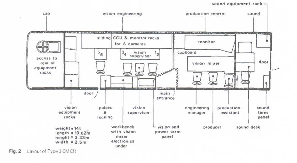
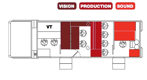
Layout of BBC Type 2 CMCR
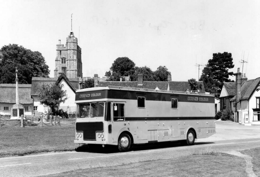
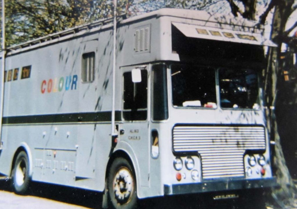
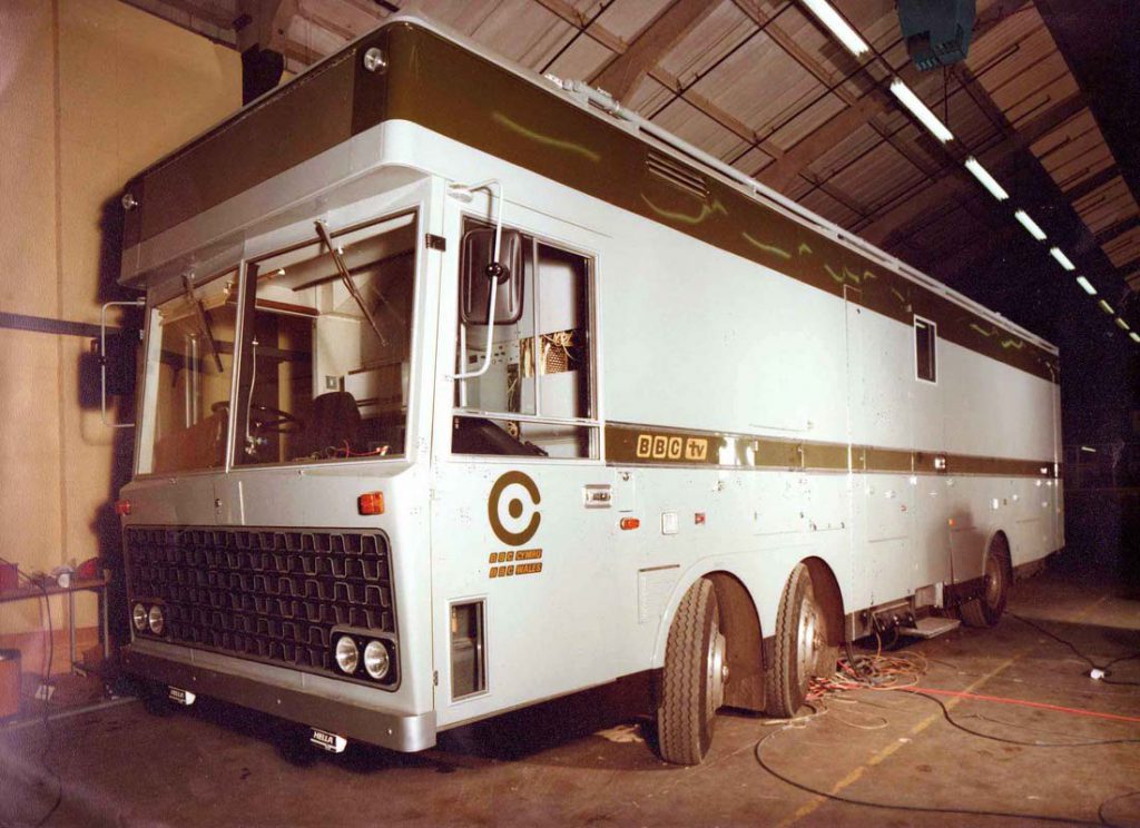
A brand new, unregistered Type-2 CMCR at Lavenham, Suffolk 1969 – photo courtesy of Richard Ellis – The Pye TVT Story.

The former LO4 – Type-2 – CMCR 4 spotted looking much the worse for wear near Boscastle, Cornwall.
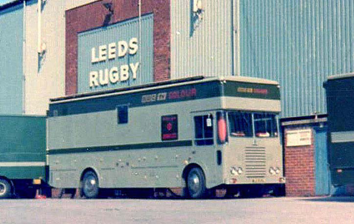
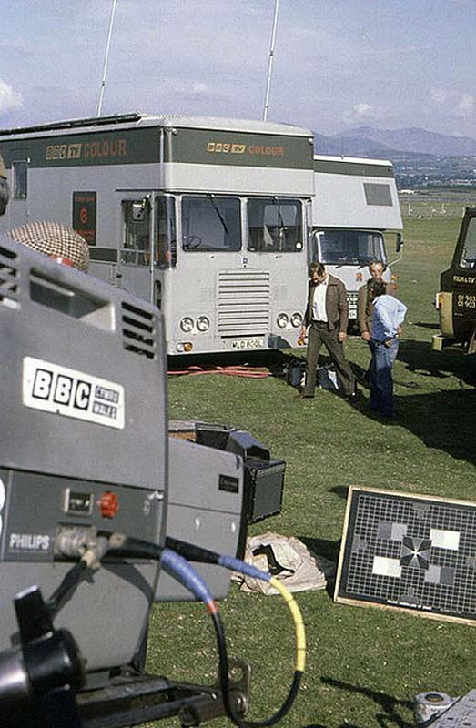
CMCR 13 at Headingley, Leeds
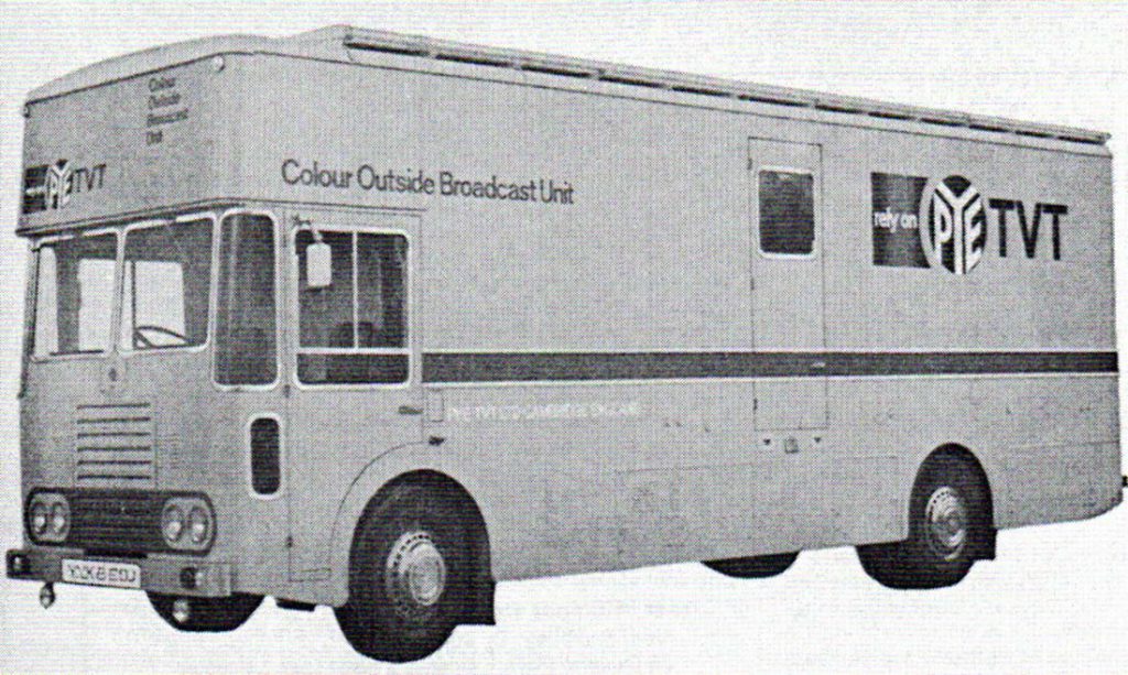
Pye Colour Demo Unit 1972 (later CMCR 13)
CMCR13, that became WA2 (Wales 2) equipped with four Philips LDK3 cameras
CMCR 14
Thank you to Gordon Bannister of BBC Nothern Ireland for the information and photos of CMCR 14, which was BBC NI first colour control room. The unit was built by Link as a demo unit in 1972. It was with BBC NI from 1973, equipped with 4 EMI 2001 cameras and a B & W caption camera. Later a couple of Ikegami HL79D cameras were added to the unit. It worked in Northern Ireland until 1988 when it was replaced by a Type 6 unit (CMCR 47) equipped with Thompson 1531 cameras
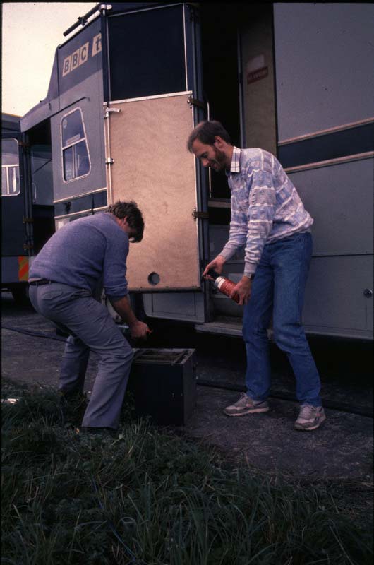
With CMCR 14 in the background, Gordon Bannister puts out a fire started by a faulty EMI PSU.
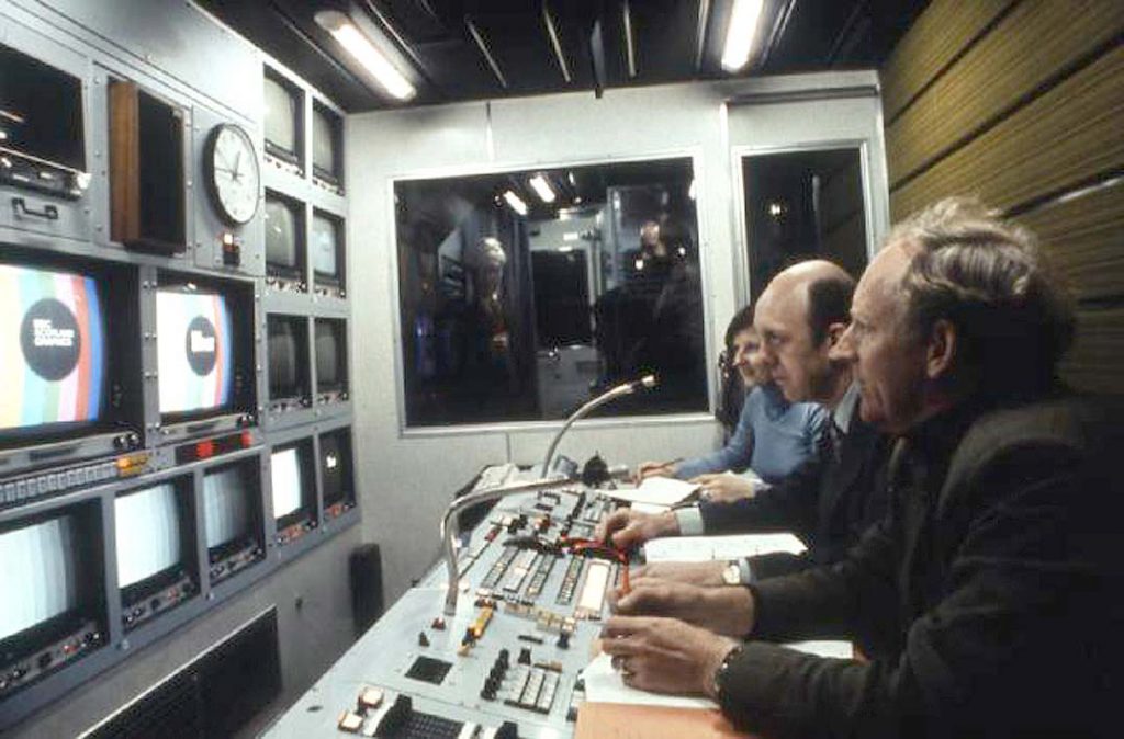
Interior CMCR 14 Photo Gordon Bannister
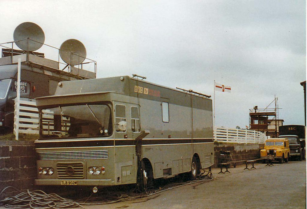
CMCR 14 on-site at the Balmoral Show, Lisburn, in 1975. Note the original registration.
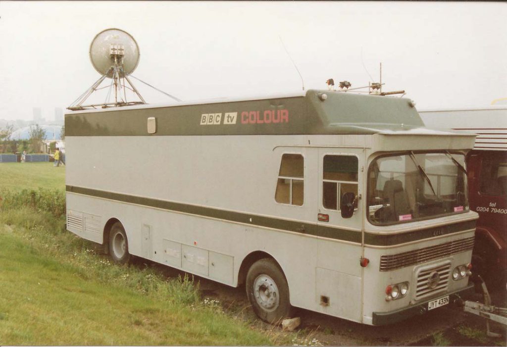
CMCR 14, in its final days in BBC service, was used as a radio-links vehicle at Gateshead Garden Festival in 1990. Note the re-registration as JYT 433N. Photo: Robin Stonestreet.
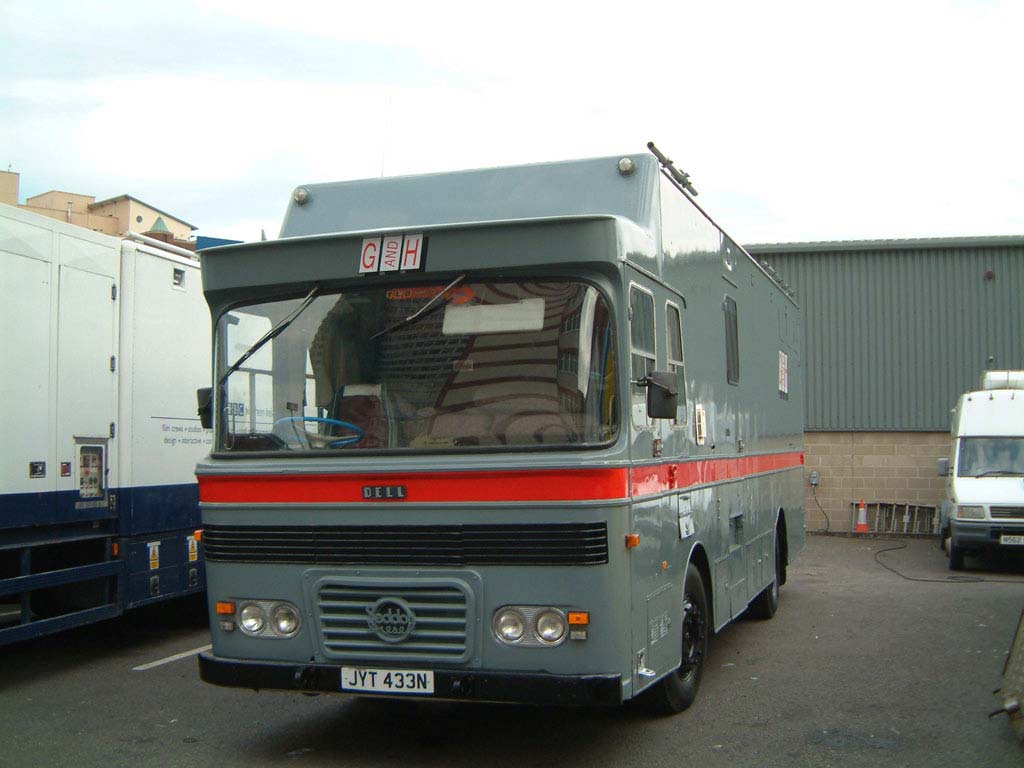
CMCR 14 seen on its return to Belfast as an independently-owned wardrobe unit. Photo: Gordon Bannister
BBC TYPE 4 – CMCR 16 – Wales 1 of 1975 – Photo courtesy of Richard Ellis -The Pye TVT Story
Production Control Scotland 1
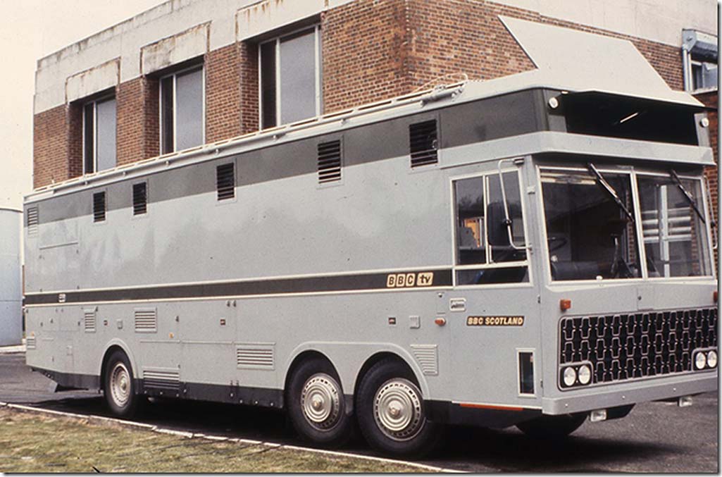
BBC Type 4 – CMCR 17 – Scotland 1 of 1975 Photo courtesy of Richard Ellis -The Pye TVT Story
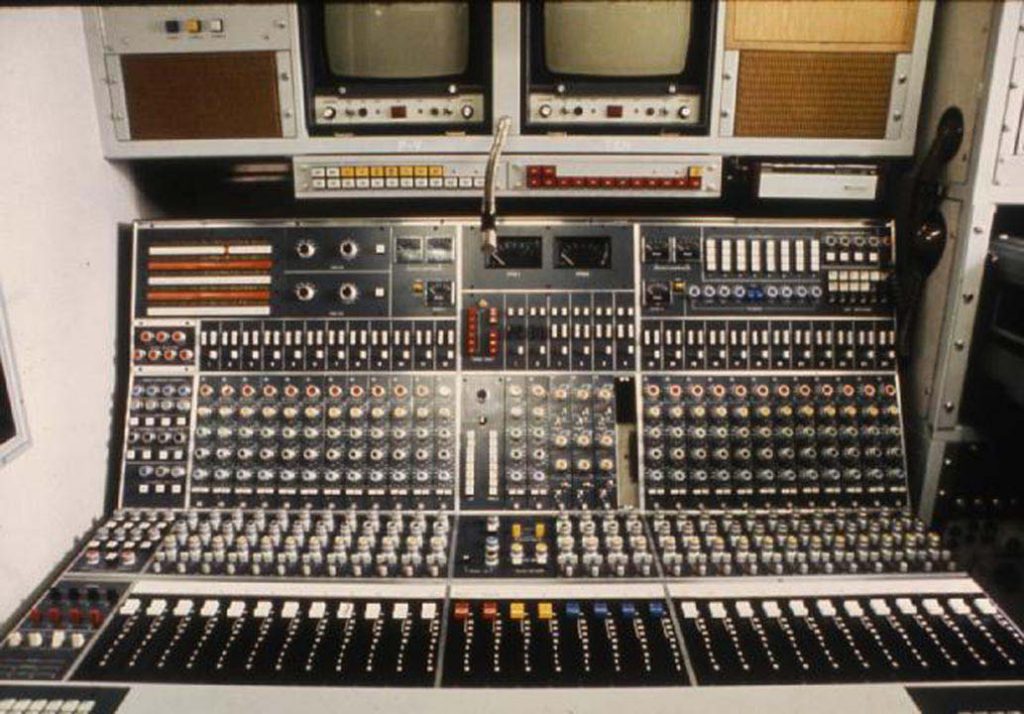
Type 4 Sound Compartment – Photo courtesy of Richard Ellis -The Pye TVT Story
North 1 – Type-5 – CMCR 36 at Leeds International Pool 1984
Type 5 at Chiswick Bridge. Photo: Andrew Browne
BBC Type-6 CMCR 48 Wales 1. Photo: Andrew Browne
North 4 Type-7 CMCR 56. Photo: Andrew Browne
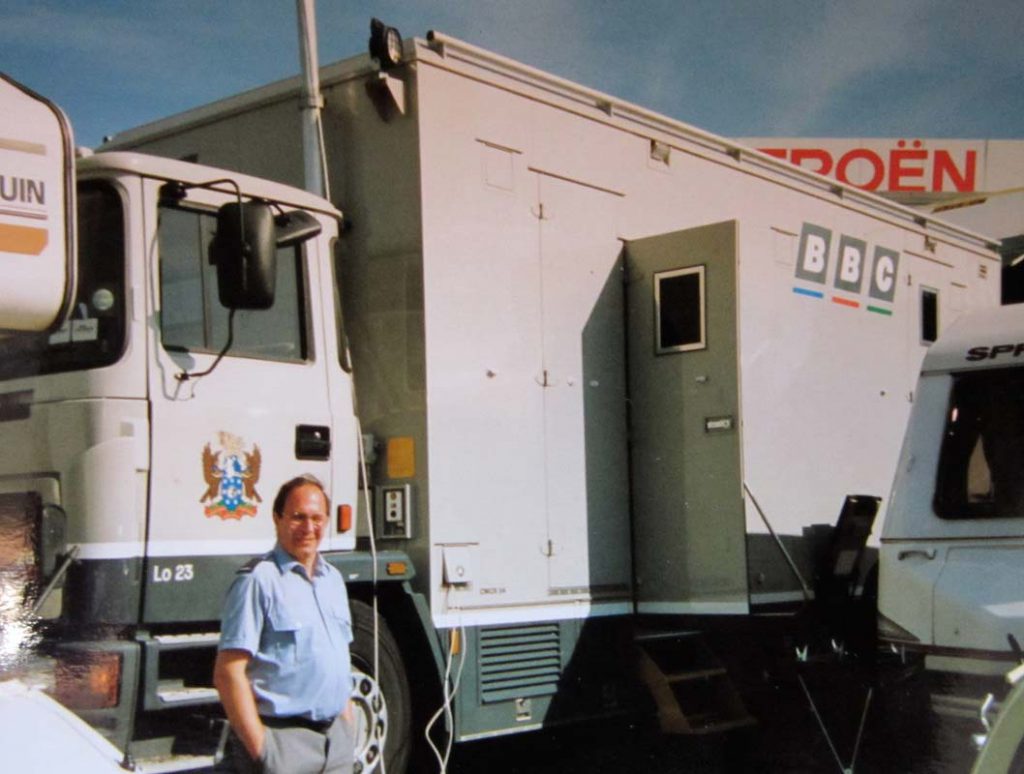
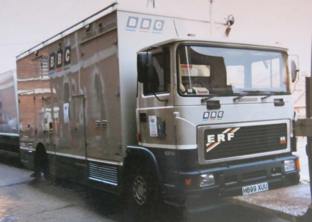
LO23 Type-7 CMCR 54. Photo: Andrew Browne
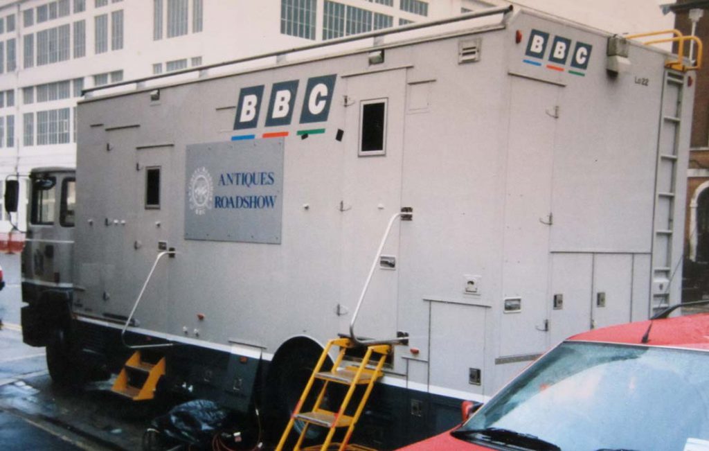
LO22 Type-7 CMCR 62. Photo: Andrew Browne

LO2 – Type-8 – CMCR 64. Photo: Andrew Browne
